Harman Kardon Allure Teardown
Contents
This is part 1 of three posts about the Harman Kardon Allure: the hardware. Part 2 covers allure-os, the firmware I wrote for it, and part 3 the open-source release of software and boards.
Introduction#
The Harman Kardon Allure has aged well; its software has not. Everything that makes the speaker “smart” sits on one plug-in module running a LinkPlay firmware from 2019, while the amplifiers, the DAC, the microphone DSP and the microcontroller for buttons and lights sit on Harman’s own boards. That split is what this project is built on: replace the module with a Raspberry Pi Zero 2 W and keep the rest. This post looks at what is inside and how the parts talk to each other.
The Allure is a smart speaker with Amazon Alexa. Harman unveiled it at IFA in Berlin on 31 August 2017, at $249.95, with sales planned for winter 2017. Harman had become a subsidiary of Samsung Electronics six months earlier, in a deal worth about $8 billion. At CES 2018 a battery-powered sibling followed, the Allure Portable.
The Allure has a translucent body, two light rings, four far-field microphones and a touch-sensitive volume ring. One light ring sits right on top, around the microphones; the second sits under the microphone array and points downward, lighting the translucent dome from inside. Harman’s spec sheet lists:
| Item | Specification |
|---|---|
| Output power | 60 W total |
| Frequency response | 40 Hz – 20 kHz |
| Drivers | 3 × 38 mm, plus a 90 mm subwoofer |
| Dimensions, weight | 166 × 166 × 193 mm, 2.5 kg |
| Power supply | 19 V, 3 A |
| Wi-Fi | IEEE 802.11 a/b/g/n/ac, 2.4 and 5 GHz |
| Bluetooth | 4.2, A2DP 1.3, AVRCP 1.5 |
Setup required Harman’s “HK Alexa Setup” app, and everything after it went through Alexa and the cloud services of LinkPlay and Amazon.
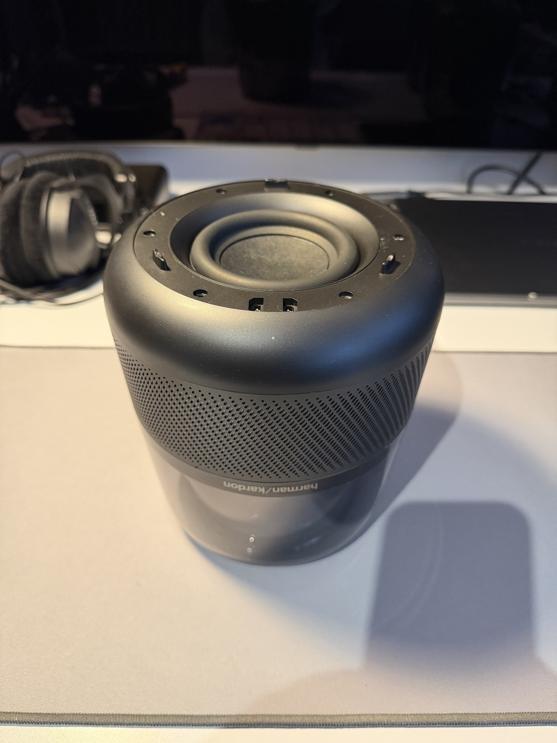
Teardown#
The Allure opens from the bottom. Under the bottom cover sits the woofer, facing down.
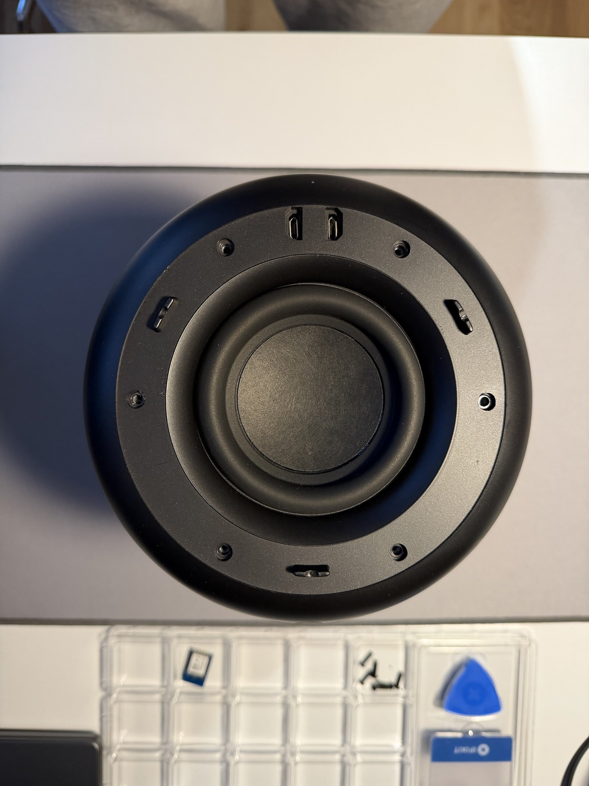
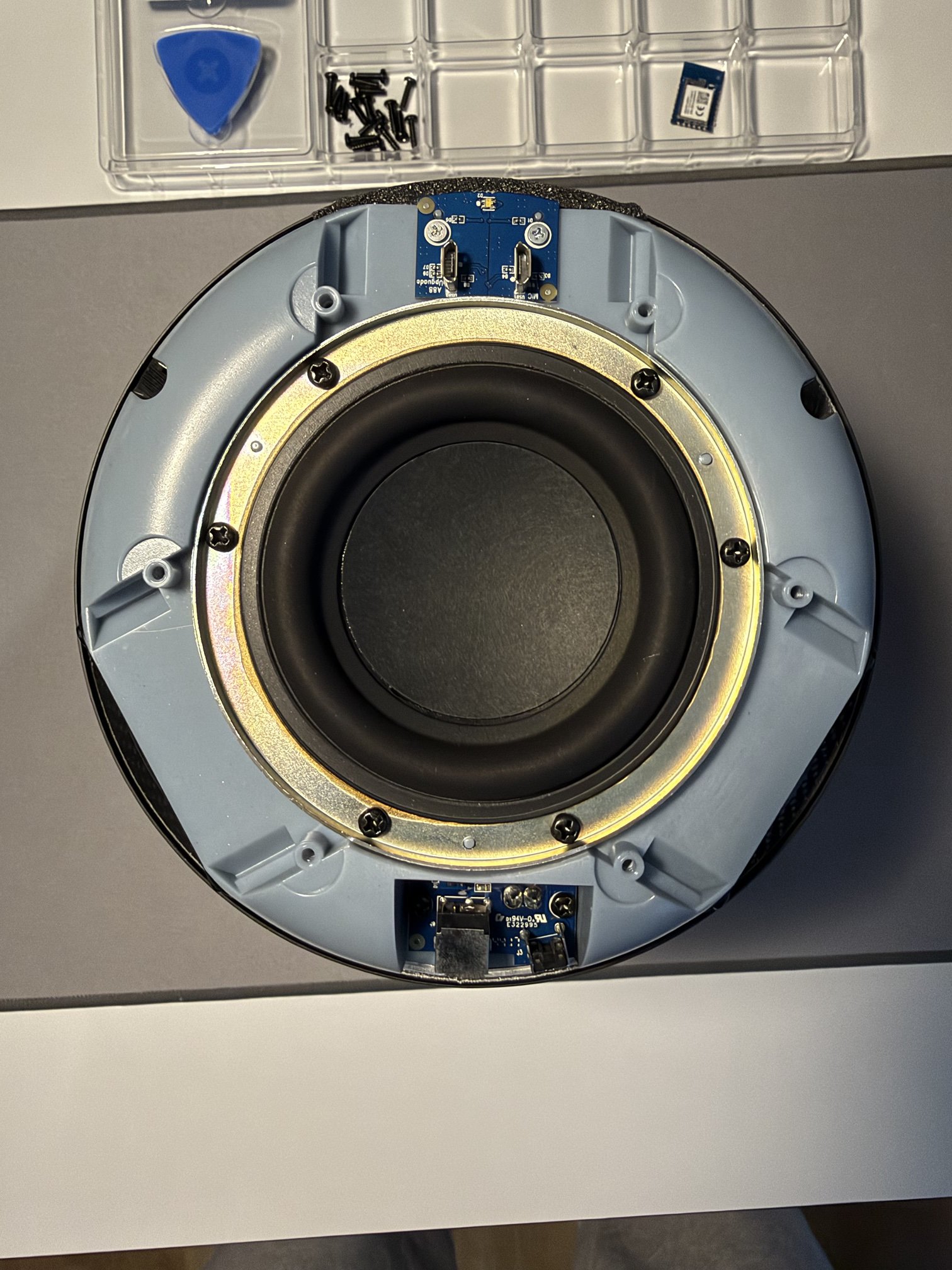
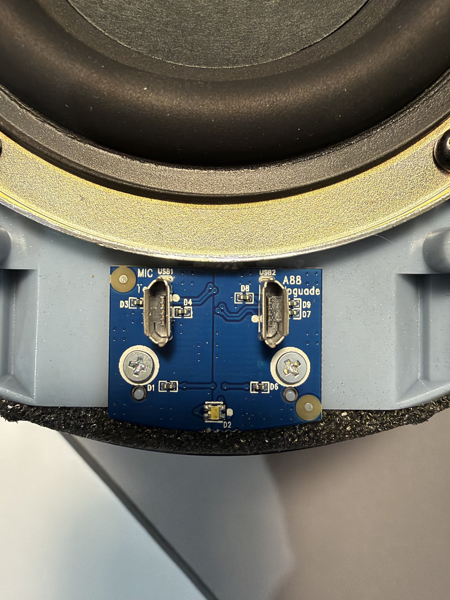
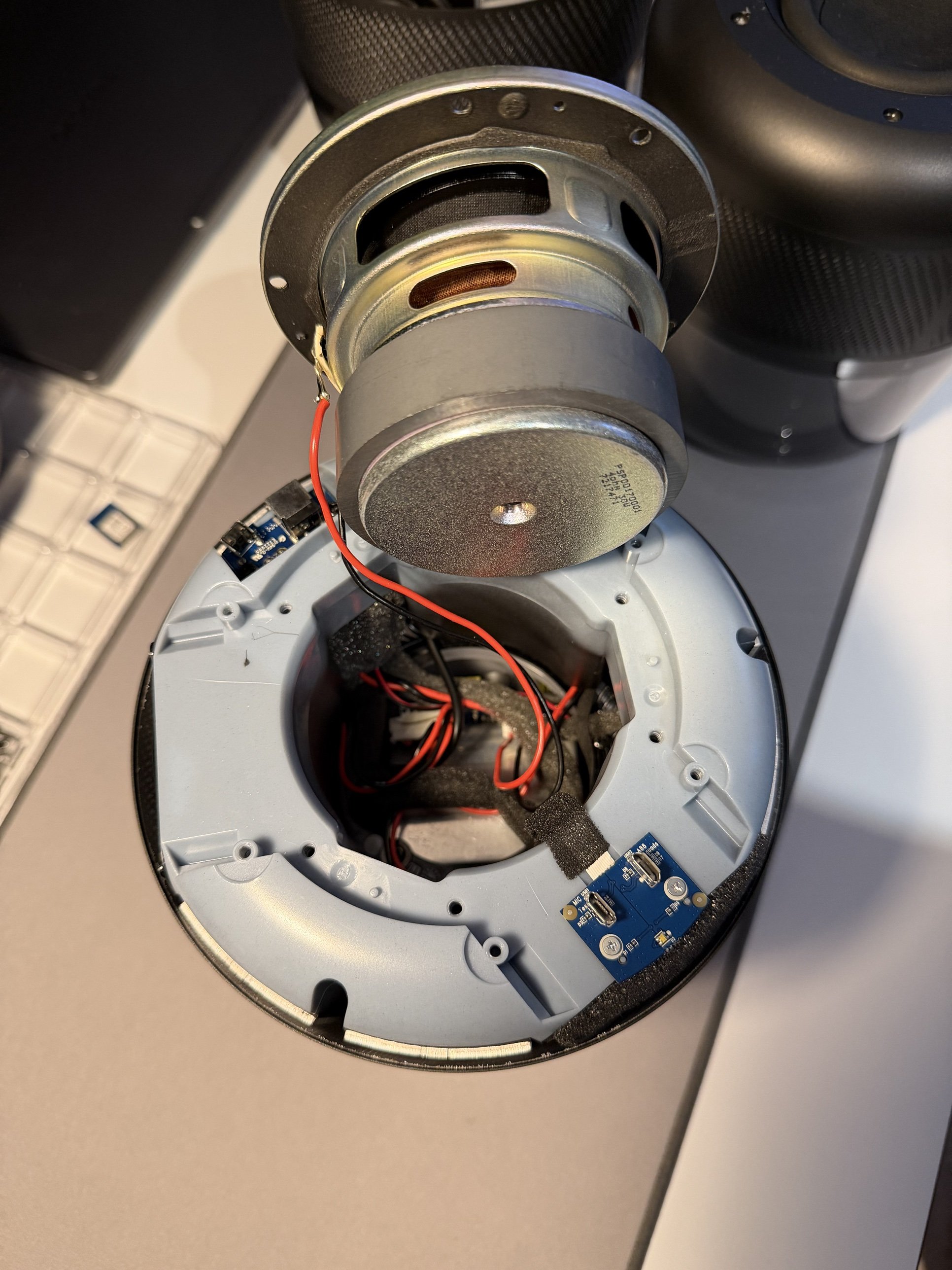
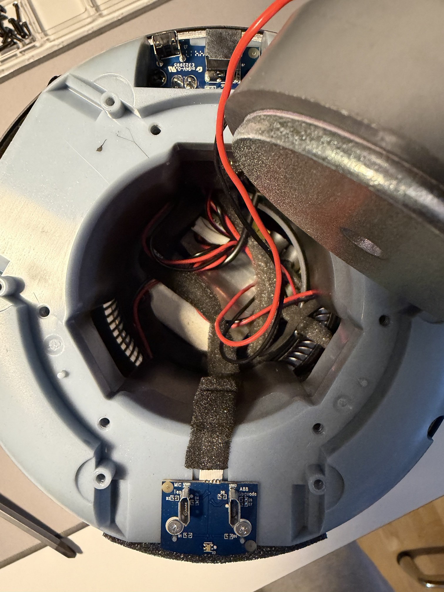
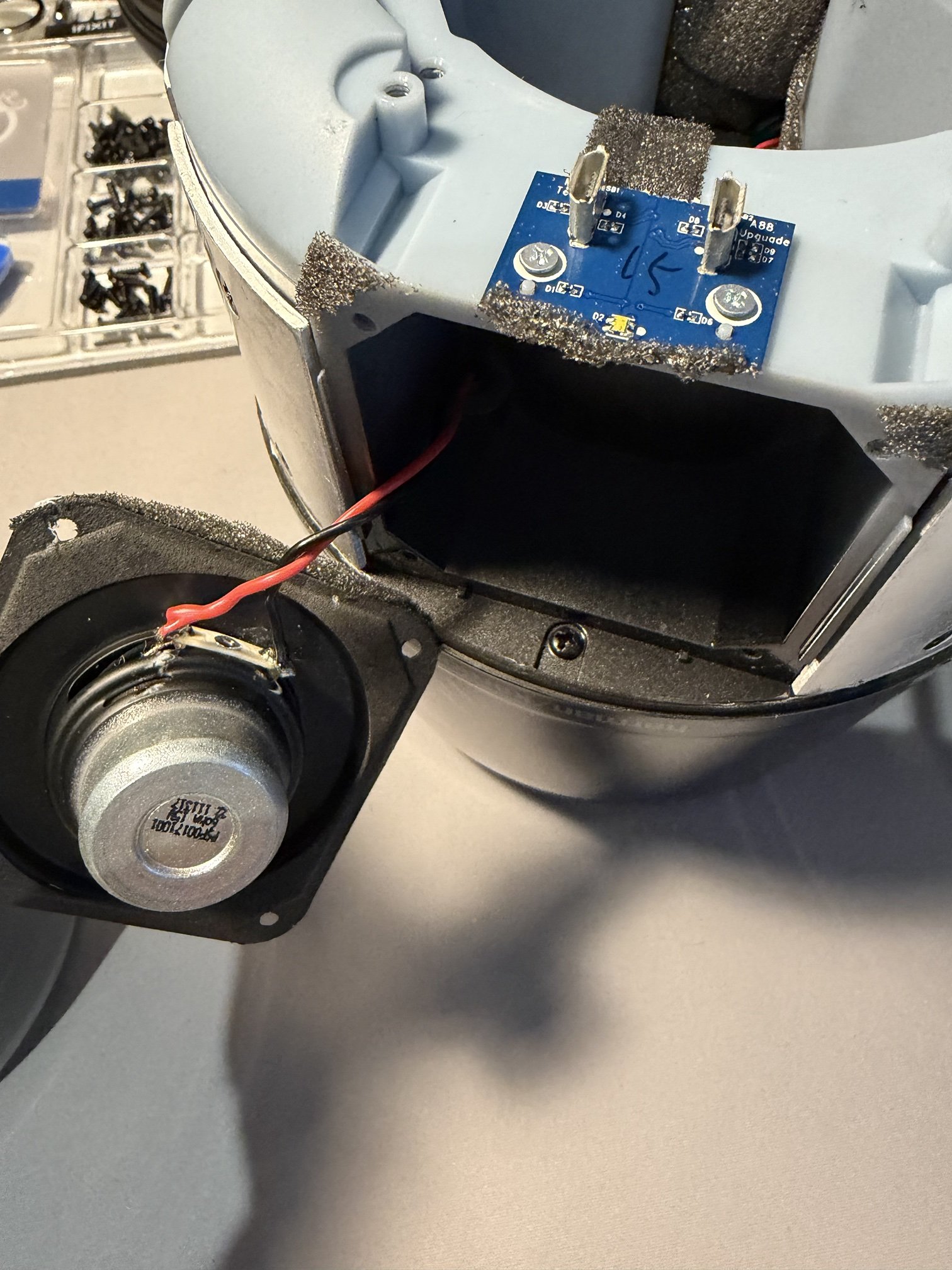
Next to the woofer are two small boards. One carries two micro-USB ports, labeled MIC Test and A88 Upgrade: factory ports for testing the microphones and flashing the A88. The other carries the DC jack and the reset button.
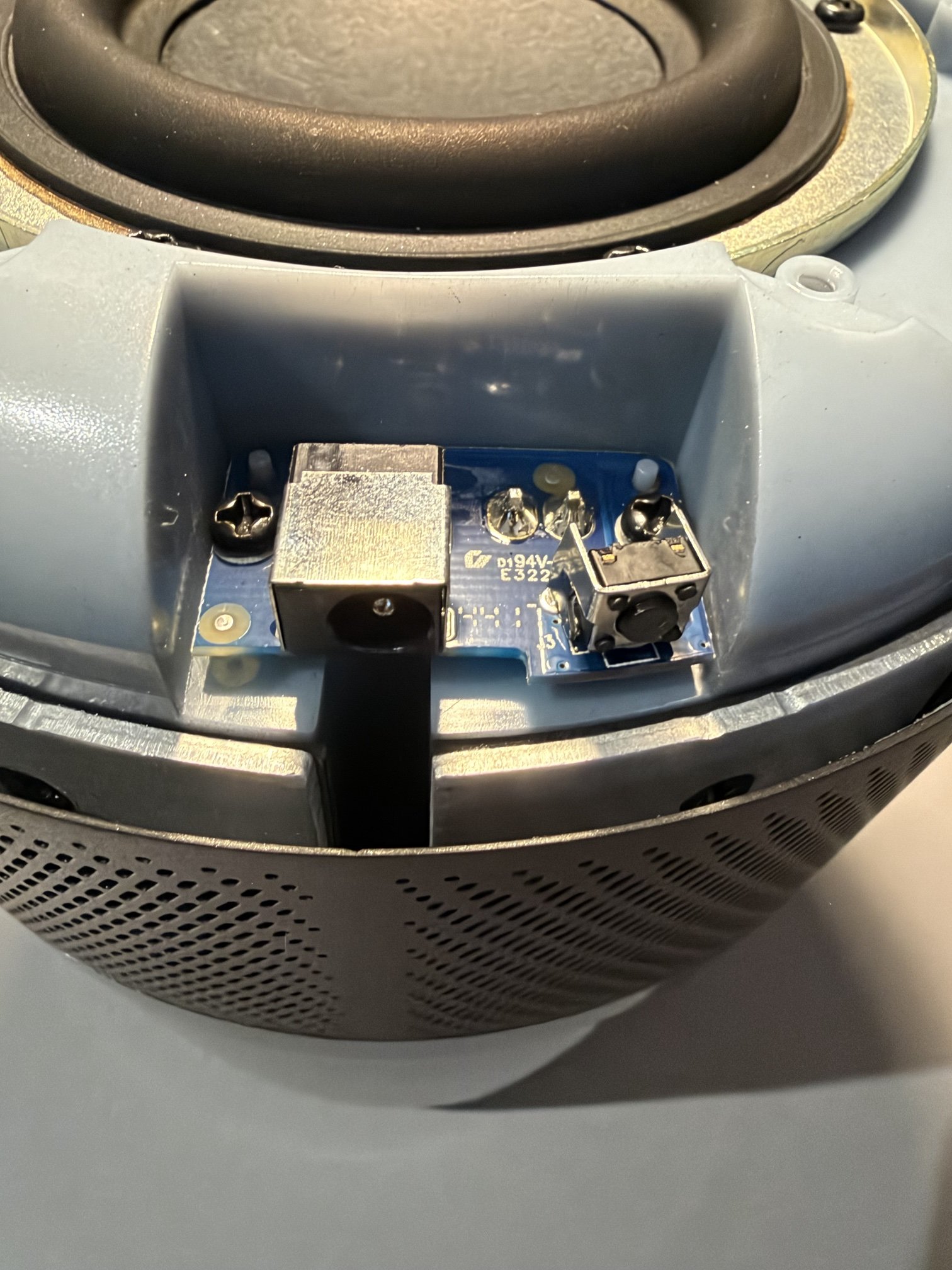
The woofer comes out after six screws. Behind it is the woofer chamber of the light blue chassis that the whole speaker is built around.
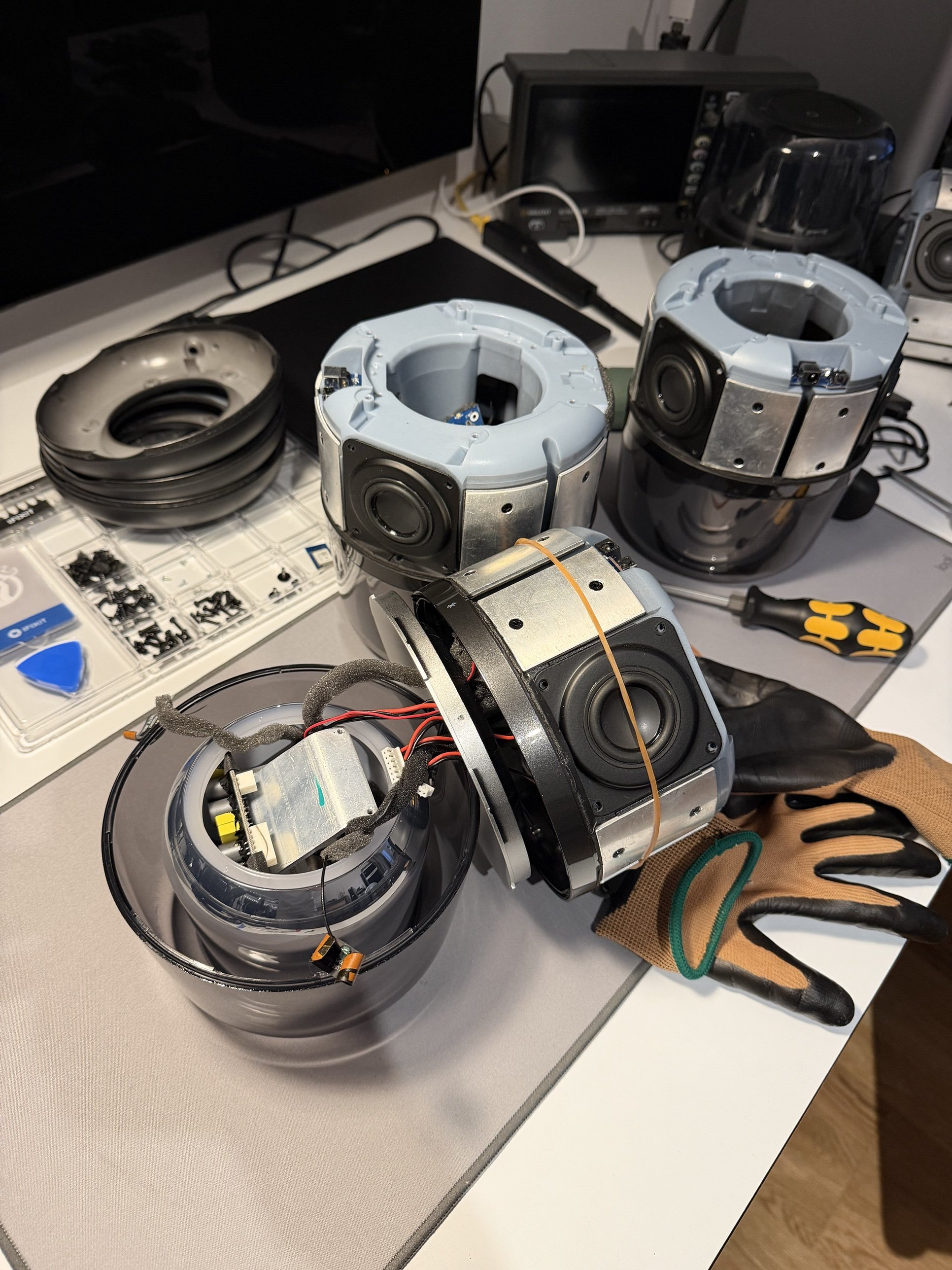
With the perforated grille band removed, the mid/high drivers are visible in the sides of the chassis, between aluminum covers.
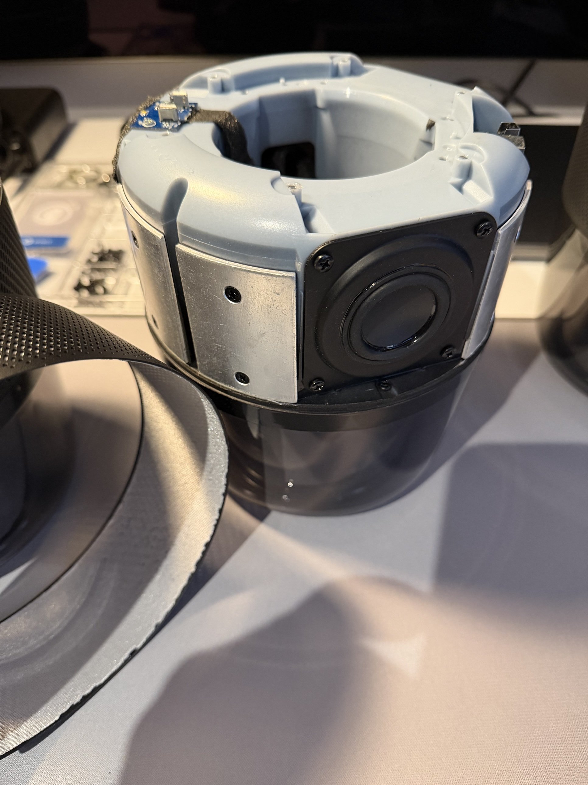
The electronics sit in the translucent top section, above the chassis. To reach them, the chassis comes off the top section with all cables still attached.
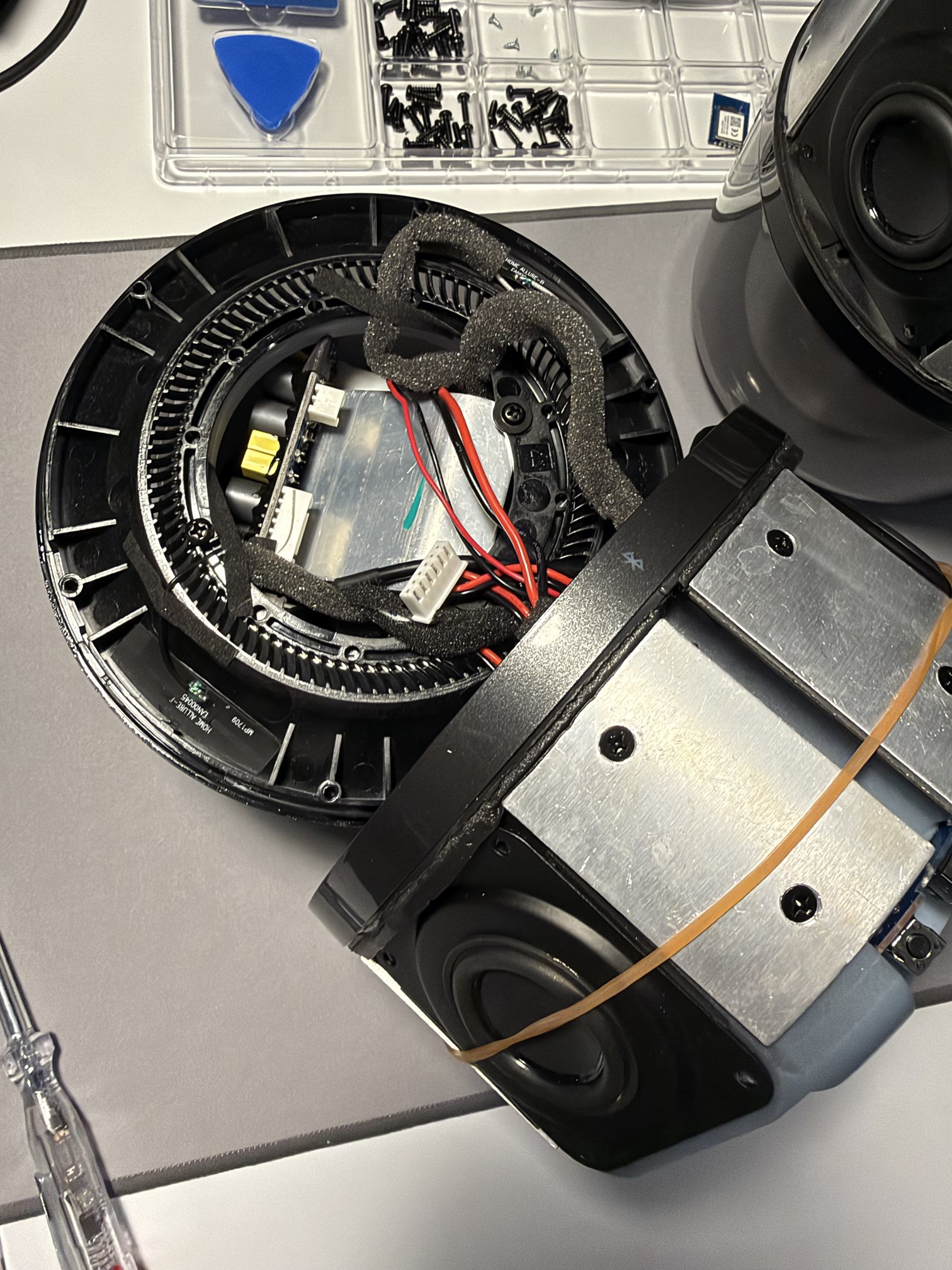
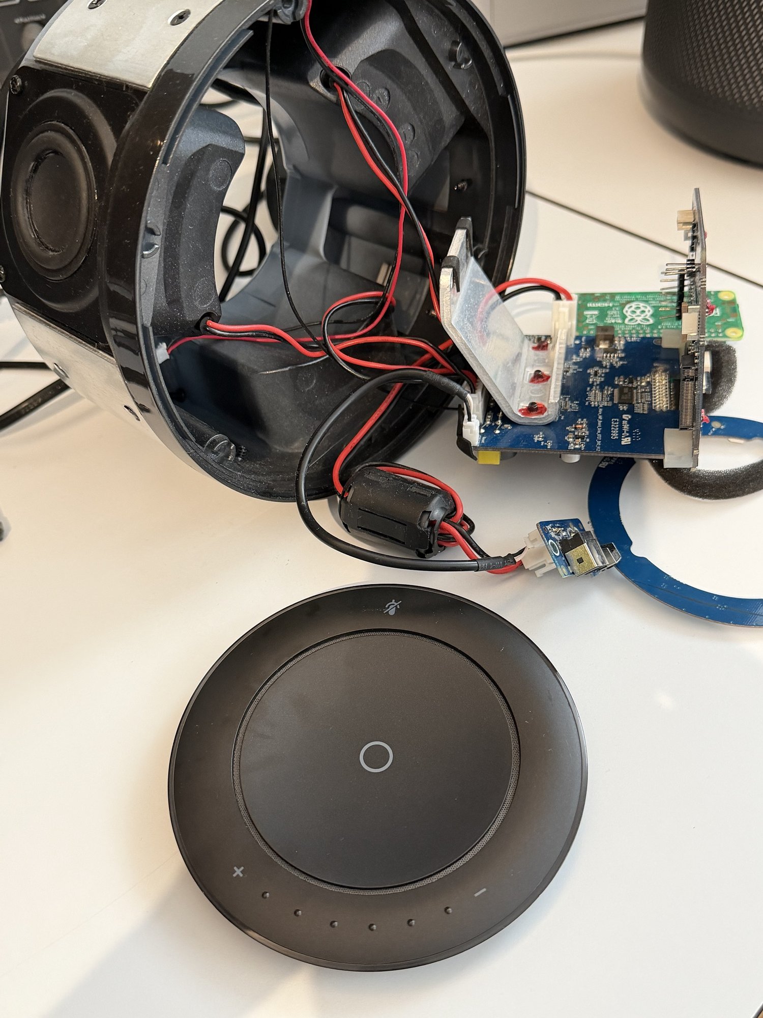
The top panel is one unit: the touch buttons, the dots of the volume ring, the microphones and the top light ring are all built into this disc.
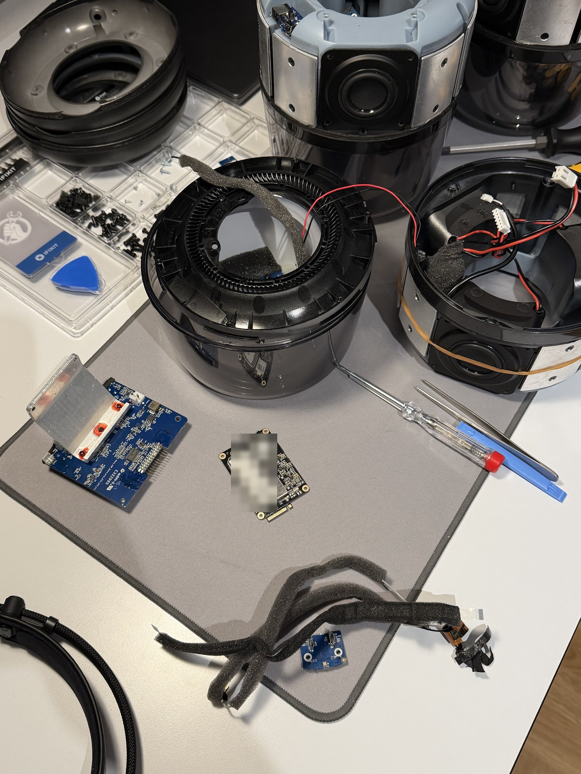
Amplifier board#
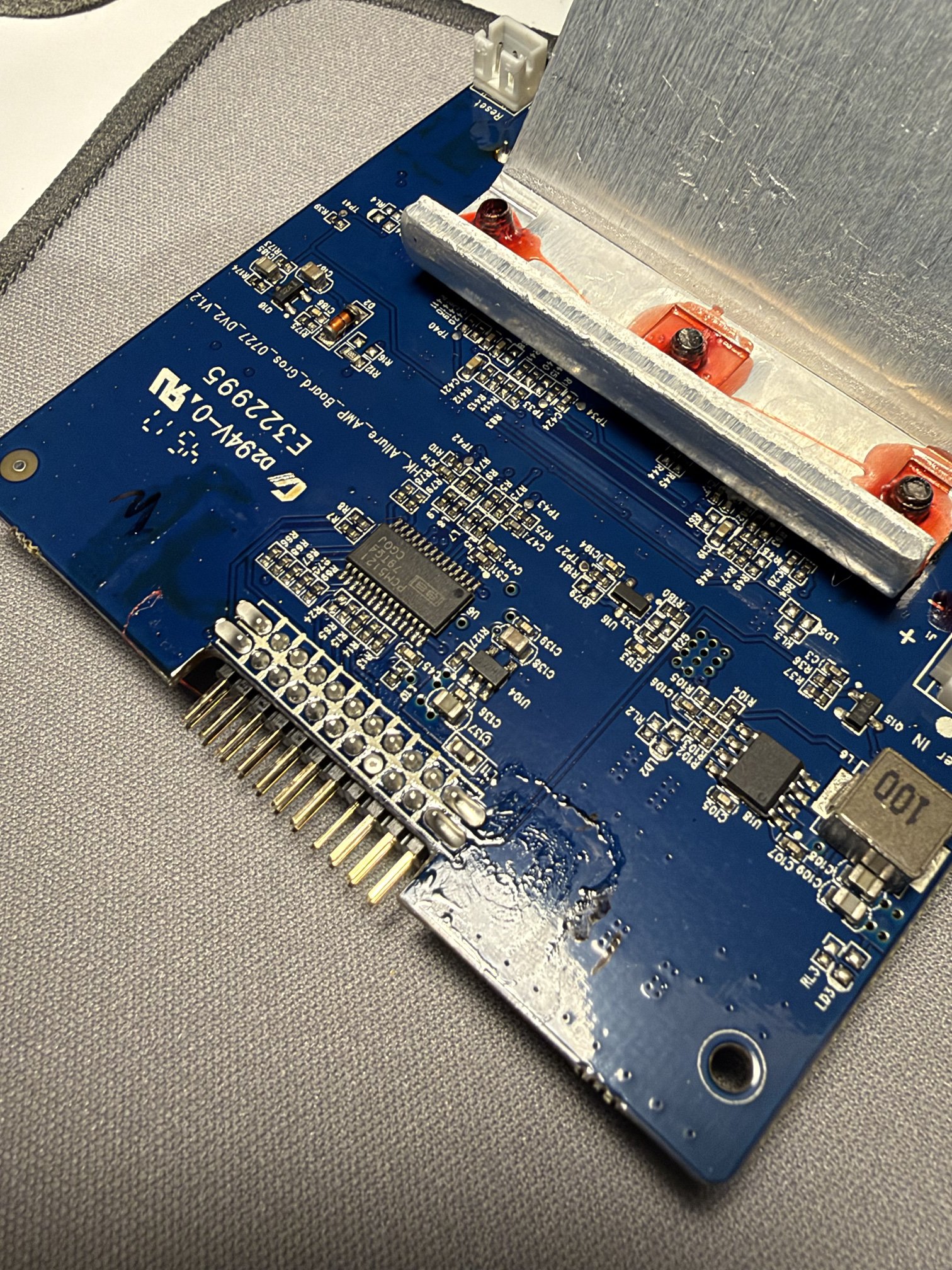
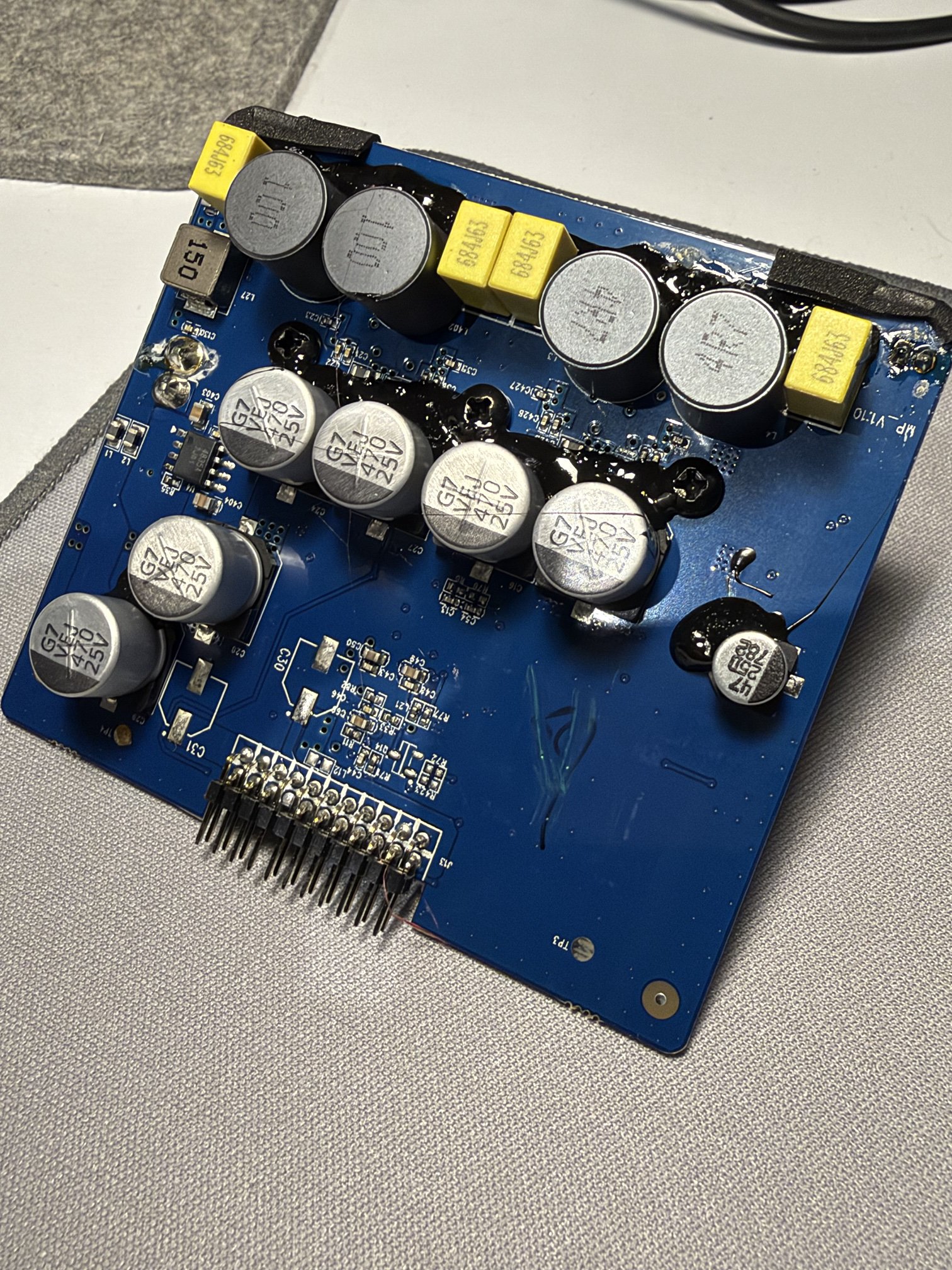
The amplifier board stands upright in the top section. Its silkscreen names it HK_Allure_AMP_Board. On the front is the TI PCM5121 DAC. Its two channels feed two amplifier channels: one for the woofer, one for the mid/high drivers. The amplifier chips sit under an aluminum heat spreader. The back carries the output filter inductors and the 470 µF supply capacitors.
Mainboard#
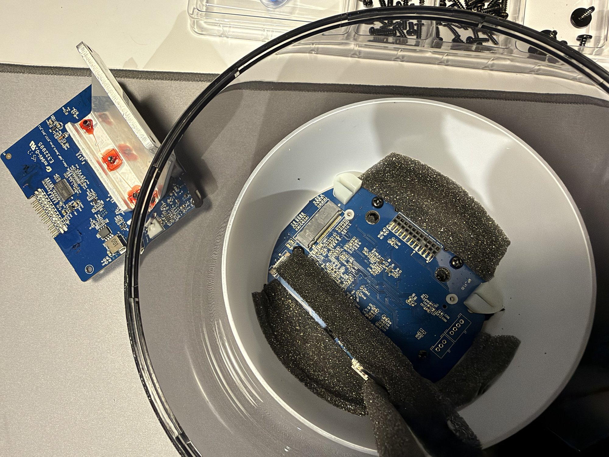
The mainboard lies flat under the top surface, covered with foam. It holds the M.2 slot for the A88, a header for the amplifier board and the cable connectors. On its underside sit the two chips that matter most after the module: the Conexant CX20924 for the microphones and the TI MSP430FR2533 for buttons and light.
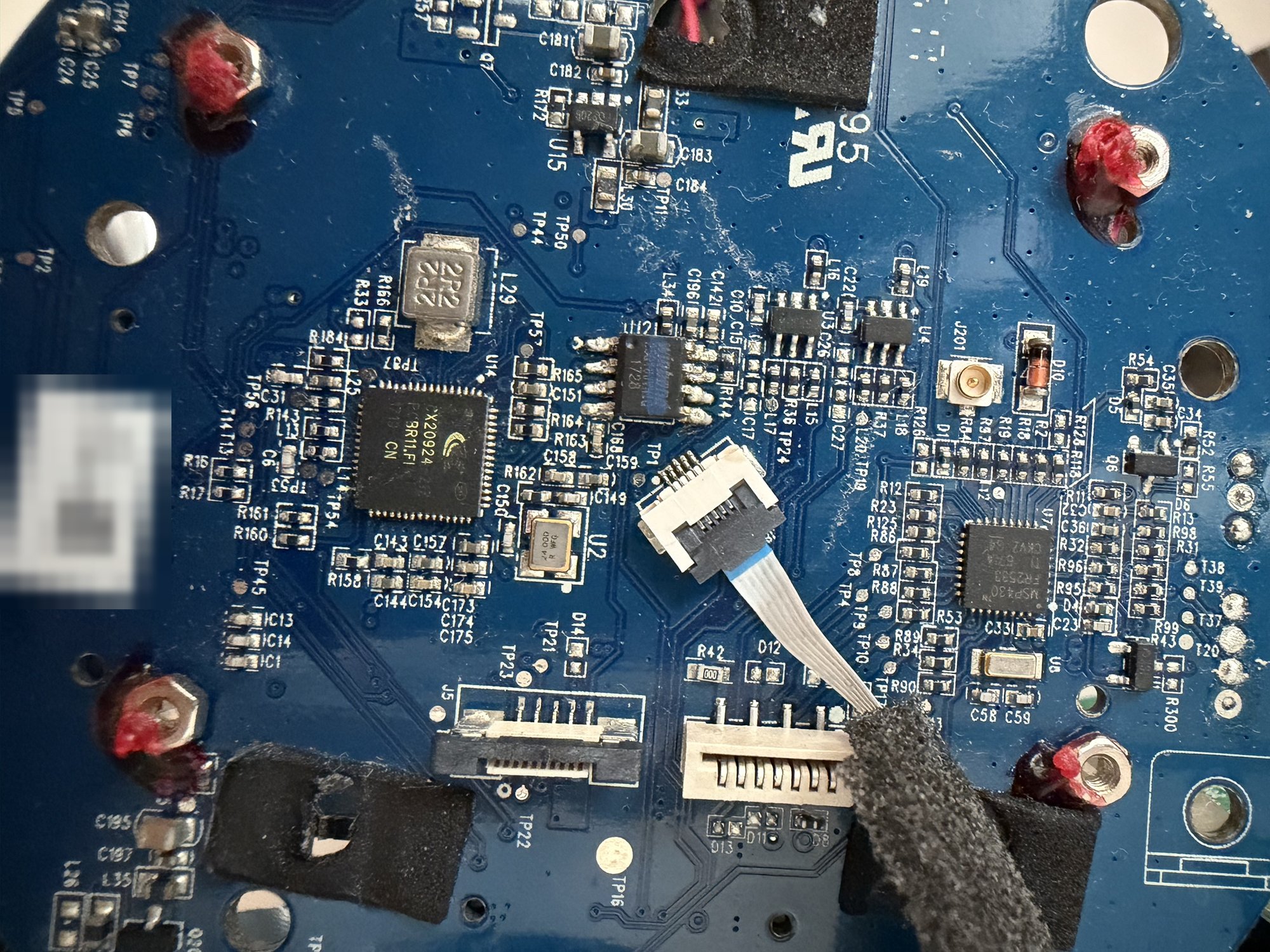
The chips#
Conexant CX20924#
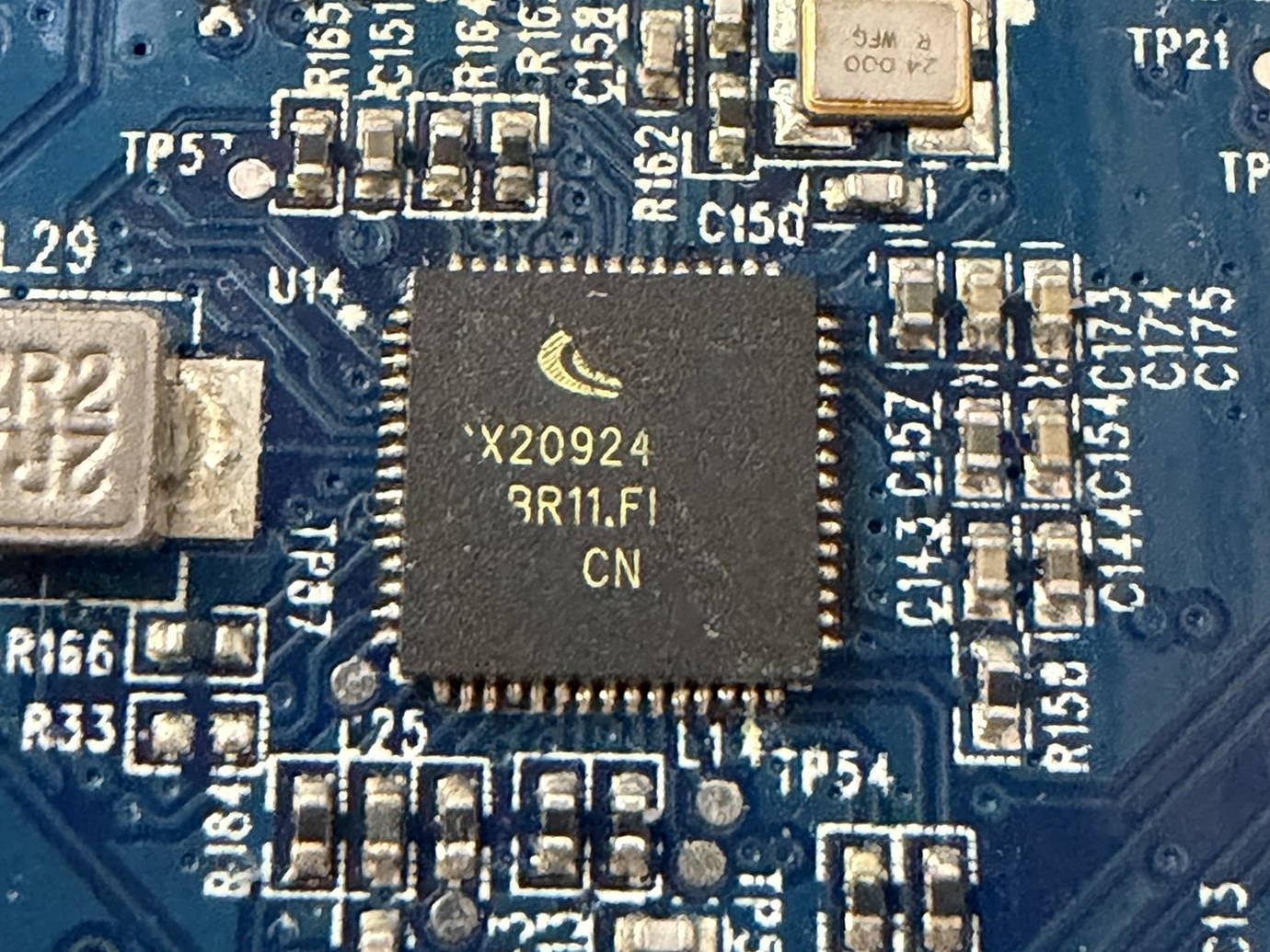
The CX20924 is the part of the Allure that hears. It belongs to Conexant’s AudioSmart line. Synaptics’ product brief calls it a “4-mic far-field voice input processor” with a dual-core 32-bit DSP and inputs for four PDM microphones. On top of that come noise suppression that Conexant calls Smart Source Pickup, full-duplex echo cancellation, and a Smart Source Locator that estimates the direction of the person speaking, all around the speaker. The chip boots its firmware from its own SPI flash and is controlled over I2C; the processed voice leaves over I2S.
The chip comes from the first wave of Alexa devices. Conexant was one of two suppliers Amazon recommended for far-field microphone kits for the Alexa Voice Service. A 2-microphone kit appeared in December 2016, followed by a 4-microphone kit with the CX20924. That kit was designed to work with Amazon’s Alexa sample project for the Raspberry Pi, and that is where the Linux driver used in part 2 comes from. In June 2017, less than three months before the Allure was announced, Synaptics agreed to buy Conexant for $300 million in cash plus stock; the CX20924 has been a Synaptics product since.
Documentation is another matter. Synaptics publishes a two-page product brief [pdf], but no datasheet: the register map, the command protocol and the boot options are not public. I asked a dozen sellers on Alibaba who listed the CX20924, some with full reels in stock. All of them could sell the chip; none could send a datasheet. The only document that comes close is a datasheet of the 2-microphone CX20921 marked “Conexant Confidential”, which circulates on datasheet sites. Everything else I know about the CX20924 comes from the stock firmware and from measuring the chip itself.
TI PCM5121 and MSP430FR2533#
The two TI parts are well documented. The PCM5121 [pdf] is a stereo DAC with a 106 dB dynamic range, I2S input and I2C control. Its PLL can derive the master clock from the I2S bit clock, so it needs no separate clock line. That matters for the replacement board, because the Raspberry Pi provides none. The DAC can process audio on its own, but only with one fixed process flow from its ROM. Harman’s tuning does not fit into it, so the Allure uses the PCM5121 as a plain converter, and the tuning runs in software on the module (part 2 takes it apart).
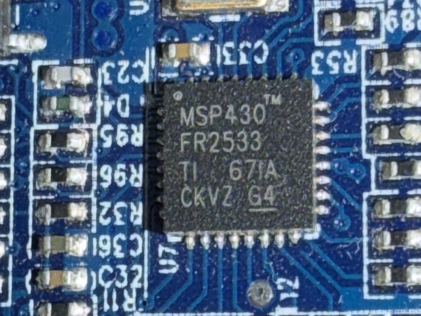
The MSP430FR2533 [pdf] is a 16 MHz FRAM microcontroller with TI’s CapTIvate capacitive touch peripheral. In the Allure it reads the touch buttons and the capacitive volume ring, controls the amplifier and drives the LEDs of both rings, and it talks to the module over a UART at 115200 baud.
LinkPlay A88#
LinkPlay Technology was founded in 2014 by engineers from Google, Broadcom, InterVideo and Harman, and it builds streaming modules and their firmware for other audio brands. Today it also sells streamers under its own brand, WiiM. A speaker maker buys the module with Wi-Fi, streaming, multiroom, a phone app and voice assistant support ready to use, and adds its own acoustics, amplifiers and industrial design. For Alexa, LinkPlay went further: according to Amazon, it supplied reference designs, schematics and mobile apps, and acted as the certification proxy that checked a product against Amazon’s acoustic and functional requirements. For the Allure this meant that Harman designed the speaker and LinkPlay supplied its brain.
The A88 is an M.2 card with key A that plugs into the mainboard. Under its shield sit the SoC, which the firmware identifies as an Amlogic A111, the NAND flash and a Wi-Fi and Bluetooth module. It runs Linux and the whole “smart” part: network, Alexa, streaming, the voice pipeline and the control of every other chip. The A111 is the entry-level part of Amlogic’s 2017 audio SoCs: four 32-bit Arm Cortex-A5 cores in 28 nm, with I2S and TDM audio interfaces. That is why everything on the module, Harman’s DSP plugin included, is 32-bit ARM code, while allure-os is a 64-bit (arm64) system; part 2 shows how the plugin still runs. I found no public datasheet for the A111 either.
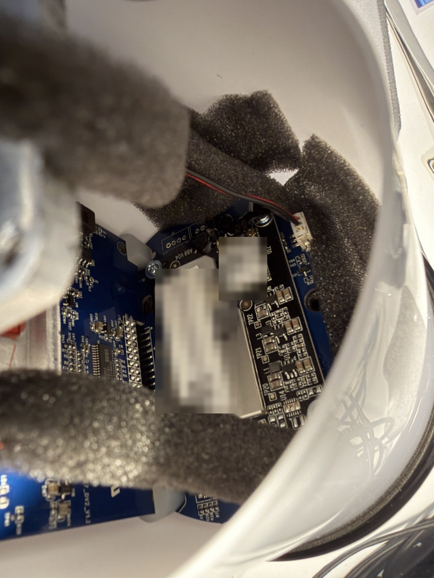
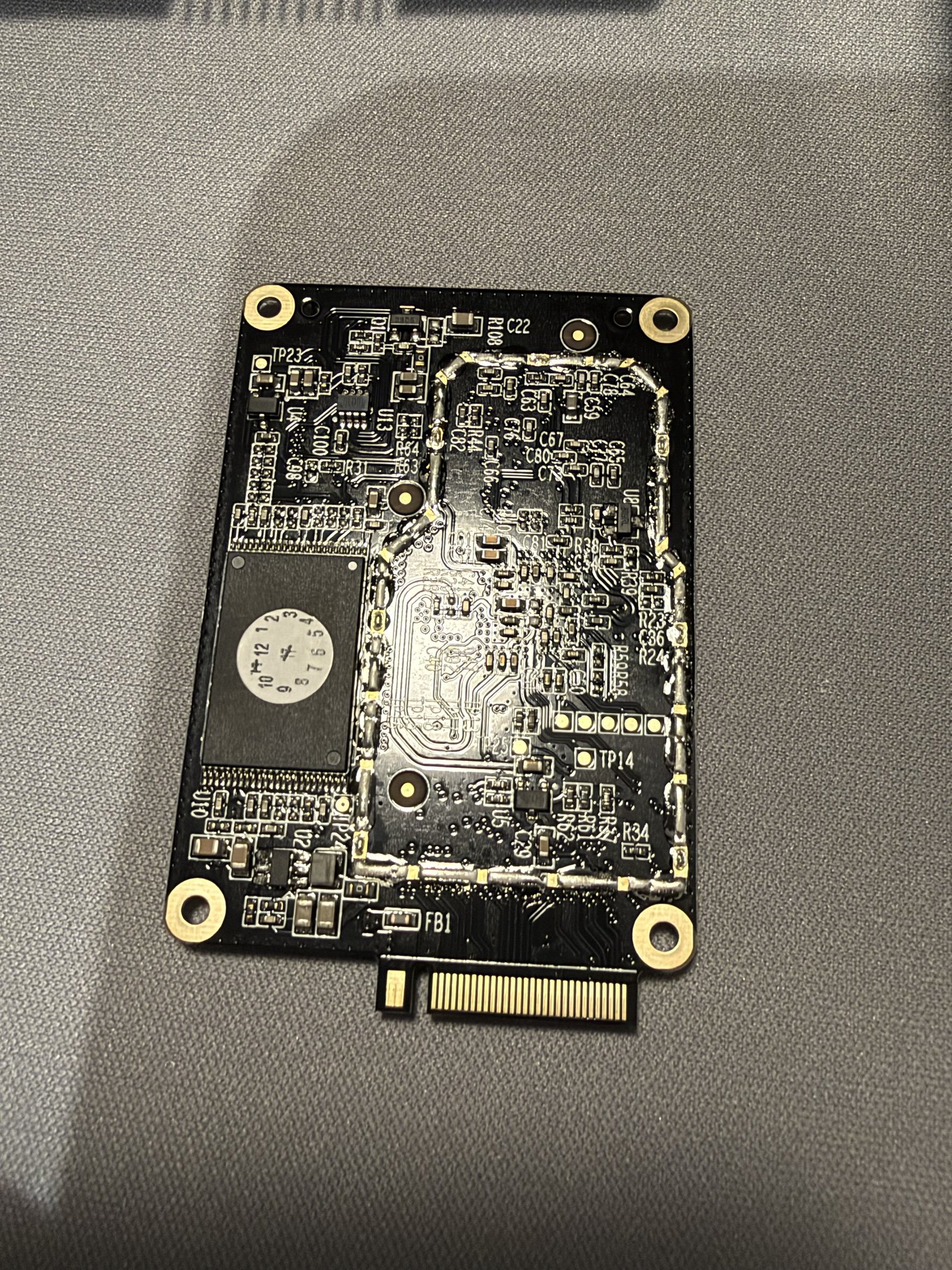
LinkPlay does not publish documentation for its modules. What made this project possible is a side effect of radio regulation. The A88 contains a Wi-Fi and Bluetooth radio, so it needed an FCC equipment authorization before it could be sold in the US, and LinkPlay filed the module’s specification with it under FCC ID 2ANOG-A88 (WiFiAudio-A88 Specification, Rev 1.5 [pdf]). That document was my only source for the pin names and signal directions of all 67 contacts and for the card itself: M.2 key A, 0.8 mm thick. Without it, the replacement board would have had to be measured from a module that was in use, contact by contact.
The A88’s card edge carries 5 V and ground, two I2C buses, two UARTs, an I2S bus with one input and one output, GPIOs, and USB, SPI, PWM and JTAG signals that the Allure leaves unused. The speaker uses a small subset of them:
| Signal | Connects |
|---|---|
| 5 V, ground | power for the module |
| I2C | the CX20924 at 0x41 and the PCM5121 at 0x4C |
| UART | the MSP430 |
| I2S out | music to the PCM5121 |
| I2S in | processed microphone signal from the CX20924 |
| GPIO | reset and wake-word pins of the CX20924 (the Allure’s CX20924 firmware leaves the wake-word pin unused) |
Part 3 shows the signals the Pi carrier uses; allure-boards lists all 67 contacts.
How the parts work together#
On the stock firmware, the A88 does all the thinking and the other chips do the work. I learned most of this from the module’s own flash; part 2 shows how I got it.
- Music passes Harman’s DSP chain, which runs on the A88 as software, and leaves the module over I2S to the PCM5121. The DSP sums the stereo signal to mono and splits it with a crossover at about 300 Hz: the left channel of the DAC carries the woofer, the right channel the mid/high drivers.
- Voice reaches the A88 already processed. The CX20924 combines the four microphones into one beam, removes the speaker’s own music with echo cancellation, and sends the result over I2S.
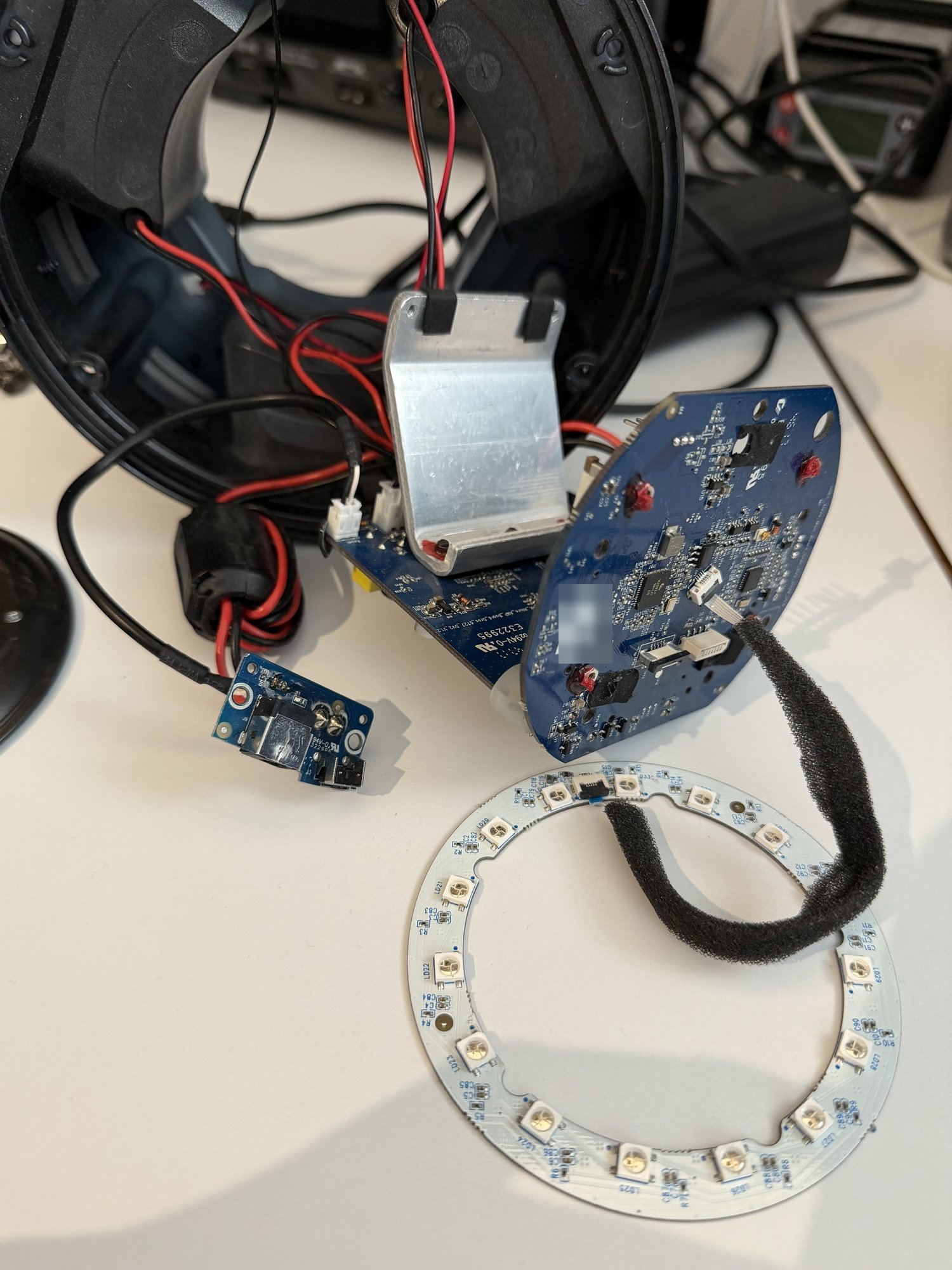
- Buttons and light go through the MSP430. It sends a short text message for every button press and every step of the volume ring, and it mutes the amplifier on command. It also switches the amplifier off by itself 60 s after a mute. The light rings turned out to be a video stream: the module sends every frame, 99 bytes of RGB for 33 LEDs, up to 25 times per second. The MSP430 itself draws only the volume arc and a fade at start-up.
The viewer below generates frames the way allure-os does: 54 bytes for the top ring around the microphones and 45 for the bottom ring that lights the dome, framed by an 11-byte marker on each side. At 121 bytes every 40 ms that is 3,025 bytes/s, about a quarter of what the 115200-baud UART carries.
Show the frame in hex
Conclusion#
The Allure is well-built hardware with a replaceable brain. Harman put the amplifiers, the microphone processing, and the buttons and light into chips on its own boards, and bought the smart part, tuning software included, as a module. Every function of the speaker passes through the module’s card edge over I2C, I2S and a UART, buses a Raspberry Pi Zero 2 W has as well. A board with the A88’s outline that carries a Pi can take the module’s place, and the speaker’s own chips keep their stock firmware.
That leaves the hard part: knowing exactly what the module said to every chip. The module was not telling; its flash would not even mount. Part 2 starts there.
Sources#
The Allure
- Harman Kardon, “Allure” spec sheet (German), 2017: docs/Harman_Kardon_Allure-spec-sheet-de.pdf, from https://support.harmanaudio.com/us/en/speakers/speakers-voice-assisted/ALLURE.html
- audioXpress, “Harman Introduces Harman Kardon Allure with Amazon Alexa”, 2 September 2017: https://audioxpress.com/news/harman-introduces-harman-kardon-allure-with-amazon-alexa
- Notebookcheck, “Samsung-owned Harman Kardon rolls out Alexa-powered speaker”, 5 September 2017: https://www.notebookcheck.net/Samsung-owned-Harman-Kardon-rolls-out-Alexa-powered-speaker.246386.0.html
- Channelnews, “Samsung Complete Harman Acquisition”, March 2017: https://www.channelnews.com.au/samsung-complete-harman-acquisition/
- PhoneArena, “Harman Kardon announces the exquisite Allure Portable smart speaker with Alexa”, 8 January 2018: https://www.phonearena.com/news/Harman-Kardon-announces-the-exquisite-Allure-Portable-smart-speaker-with-Alexa_id101444
Conexant CX20924
- Synaptics, “CX20924 product brief”, 2017: docs/Synaptics_CX20924-product-brief.pdf, from https://www.synaptics.com/products/far-field-voice-dsp/cx20924-product
- Conexant, “AudioSmart 4-Mic Development Kit for Amazon AVS”, product brief: https://www.synaptics.com/sites/default/files/DS20924_ProductBrief.pdf
- Voicebot.ai, “Synaptics Buys Amazon Echo Microphone Supplier Conexant”, 13 June 2017: https://voicebot.ai/?p=4231
- Synaptics, press release on the Conexant acquisition (Exhibit 99.1 to Form 8-K), 12 June 2017: https://www.sec.gov/Archives/edgar/data/0000817720/000119312517201430/d408106dex991.htm
Texas Instruments
- Texas Instruments, “PCM512x” datasheet SLAS763C: docs/TI_PCM5121-datasheet.pdf, from https://www.ti.com/product/PCM5121
- Texas Instruments, “MSP430FR263x, MSP430FR253x” datasheet SLAS942E: docs/TI_MSP430FR2533-datasheet.pdf, from https://www.ti.com/product/MSP430FR2533
LinkPlay A88
- LinkPlay, “About us”: https://www.linkplay.co/aboutus.html
- Amazon Alexa blog, “How Linkplay Will Enable Dozens of Connected Products with Amazon Alexa in 2017”, 6 February 2017: https://developer.amazon.com/blogs/alexa/post/9aa3774e-95c6-461a-9d52-3c54ed3be563/how-linkplay-will-enable-dozens-of-connected-products-with-amazon-alexa-in-2017
- CNX Software, “Amlogic A111, A112 & A113 Processors are Designed for Audio Applications, Smart Speakers”, 9 September 2017: https://www.cnx-software.com/2017/09/09/amlogic-a111-a112-a113-processors-are-designed-for-audio-applications-smart-speakers/
- Linkplay, “WiFiAudio-A88 Specification”, WMB20170414 Rev 1.5, 2 April 2018: docs/LinkPlay_A88-specification.pdf, from the FCC equipment authorization database, FCC ID 2ANOG-A88
- allure-boards, pinout of all 67 contacts: https://git.zaage.it/robert/allure-boards/src/branch/main/docs/pinout.md